20% Bonus On your First Rechargeclose

Choqué ! Le secret de l'utilisation de la 3D pour créer de l'animation 2D enfin révélé

En tant qu'amateur d'anime, vous êtes-vous déjà demandé comment les animations étaient réalisées ? En particulier les animations 2D qui sont réalisées en 3D. Dans cet article, le meilleur fournisseur de services de rendu cloud CPU & GPU, Fox Renderfarm, vous révèle les secrets méconnus de l'utilisation de la 3D pour créer de la 2D. Une découverte garantie pour vous étonner !

La fille au style bande dessinée met sa main devant son visage et fait un geste mignon, comme si elle était un peu timide face à la caméra…

Les secrets cachés de l'utilisation de la 3D pour faire de la 2D 1

Les amateurs d'anime ont toujours été frappés par des compositions similaires. En effet, une telle perspective intime permet de se sentir infiniment plus proche des personnages à l'écran.

Mais une fois que l'on connaît la vérité, on se sent très loin d'eux.

Les secrets cachés de l'utilisation de la 3D pour faire de la 2D 2

Un personnage tout à fait normal dans le plan, ressemblant à un monstre à main géante sous d'autres angles.

Il s'agit d'une histoire interne dont beaucoup d'acteurs de l'industrie de l'animation 3D évitent de parler. Ce que vous voyez n'est peut-être pas aussi bon qu'il n'y paraît :

Les secrets cachés de l'utilisation de la 3D pour faire de la 2D 3

La vérité "brutale" des coulisses qui pourrait briser le rêve de certains fans d'ACGN.

Les secrets cachés de l'utilisation de la 3D pour faire de la 2D 4

Et ce ne sont là que quelques-uns des éléments qui entrent en jeu dans l'animation 3D.

En tant que spectateurs, nous sommes souvent frappés par l'expressivité des animations à l'écran, mais il est difficile de penser aux astuces "trompeuses" inattendues qui se cachent derrière...

Par exemple, ces personnages à l'allure mignonne et câline peuvent avoir un modèle de bouche tordue.

Les secrets cachés de l'utilisation de la 3D pour faire de la 2D 5

Récemment, un passionné d'anime japonais, さんご, a annoncé son anime autoproduit, Bite the Bullet.

Les secrets cachés de l'utilisation de la 3D pour faire de la 2D 6

Dès sa sortie, l'anime est rapidement devenu un sujet brûlant dans la communauté japonaise de l'anime. La première chose que les gens ont admirée, c'est la haute qualité qu'il affiche.

Mais ce n'est pas tout. Avec cela, l'auteur さんご a partagé une partie du processus de production 3D de Bite the Bullet.

Ce que ces images du processus ont révélé a surpris de nombreux spectateurs : par exemple, certaines images d'animation où le personnage "parle de côté" cachent en réalité un modèle de bouche déformé.

Les secrets cachés de l'utilisation de la 3D pour faire de la 2D 7

Le plan esthétique de la jeune fille regardant vers le bas dépend de l'interprétation de l'homme monstrueux.

Les secrets cachés de l'utilisation de la 3D pour faire de la 2D 8

Le mystère de l'animation 3D a été levé avec l'apparition de ces images de production. Les vérités "brutales" ont été révélées à un grand nombre d'utilisateurs, qui ont soupiré "Ah, c'est donc comme ça...".

Les secrets cachés de l'utilisation de la 3D pour faire de la 2D 9

Mais dans le cas de l'animation 3D, il ne s'agit là que de la technique de "tromperie" la plus élémentaire.

Les secrets cachés de l'utilisation de la 3D pour faire de la 2D 10

Comme nous l'avons vu, la plupart des anime ont un aspect qui ne nous semble pas étrange, sauf si nous y réfléchissons.

Le personnage montre un visage de côté, mais une bouche complète est visible.

Les secrets cachés de l'utilisation de la 3D pour faire de la 2D 11

C'est une façon de présenter le tableau de manière à en réduire le coût. Avec son utilisation intensive, il est devenu un phénomène qui n'est pas rare pour les téléspectateurs.

Certaines animations 3D (notamment en cel-shading) doivent volontairement incliner la bouche à un angle précis lors de l'ajustement du modèle afin d'obtenir le même effet.

Cette façon de dessiner est plutôt contre-intuitive, mais c'est l'une des techniques courantes de l'animation 3D : "détruire" l'intégrité du modèle lui-même au profit de l'expressivité.

En bref, le modèle n'est peut-être pas aussi "harmonisé" que vous le pensez, là où l'observateur ne peut pas le voir.

Les secrets cachés de l'utilisation de la 3D pour faire de la 2D 12

À mesure que de plus en plus de créateurs d'animation 3D dévoilent le processus de réalisation de leurs œuvres, les secrets qui se cachent derrière commencent à être révélés.

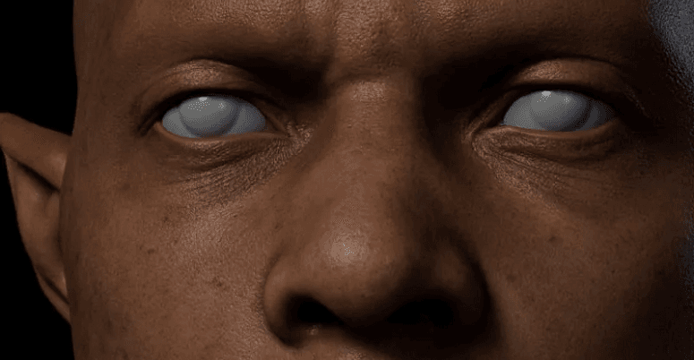
Par exemple, dans le résultat final, on trouve une image assez puissante de rugissement.

Les secrets cachés de l'utilisation de la 3D pour faire de la 2D 13

Mais cela peut paraître un peu bizarre sur la face avant.

Les secrets cachés de l'utilisation de la 3D pour faire de la 2D 14

鈴木大介, directeur CG de l’anime Bubuki/Buranki, a expliqué en détail une scène de la production : "Cette image utilise un plug-in pour ajouter des coups de pinceau aux lignes de contour, tandis que les dents postérieures, absentes du modèle, ont été remodelées et intégrées. C’est un exemple typique - le modèle 3D a été affiné pour ressembler à de la 2D."

Les secrets cachés de l'utilisation de la 3D pour faire de la 2D 15

Le spectateur ne peut voir que l'image finale. L'artiste doit souvent s'efforcer de rompre la cohérence du modèle afin de tirer le meilleur parti d'un angle particulier.

Les secrets cachés de l'utilisation de la 3D pour faire de la 2D 16

Pour la plupart des productions 3D, la réalité peut être très différente de ce à quoi on pourrait s'attendre dans des endroits qui ne sont pas visibles pour le spectateur.

Un joueur a exploré le jeu Dragon Ball FighterZ et est connu pour avoir révélé certains contenus invisibles aux spectateurs occasionnels.

Dragon Ball FighterZ est un jeu de combat dynamique publié par Bandai Namco Holdings. En tant qu’adaptation de manga, il met fortement l’accent sur la performance des combats en jeu et a reçu de nombreux éloges pour cela.

Bien que le jeu adopte une perspective traditionnelle de combat horizontal en 2D, les personnages sont modélisés en 3D, avec de brefs changements de perspective et des mises en scène spécifiques selon les compétences utilisées.

Les secrets cachés de l'utilisation de la 3D pour faire de la 2D 17

Un YouTubeur du nom de sigmaG19 a effectué quelques manipulations pour corriger la perspective du jeu et a ensuite partagé des images plus "réalistes" du jeu.

C'est par contraste que l'on comprend comment certaines performances extrêmement tendues sont réalisées. L'exemple le plus classique est l'animation du grand mouvement de Son Gohan. En action réelle, il se présente comme suit :

Les secrets cachés de l'utilisation de la 3D pour faire de la 2D 18

L’animation offre délibérément un gros plan sur les mains du personnage, rendant le mouvement global extrêmement intense. Et si vous regardez cette scène sous une perspective fixe, vous verrez que l’effet ci-dessus est en réalité obtenu en augmentant drastiquement la taille des mains :

Les secrets cachés de l'utilisation de la 3D pour faire de la 2D 19

Il existe plusieurs séquences d'animation similaires. Une fois la caméra et la perspective absentes, l'effet visuel réel devient légèrement étrange.

Les secrets cachés de l'utilisation de la 3D pour faire de la 2D 20

Certains acteurs du secteur de l'animation qualifient cette technique de "tromperie nécessaire".

La "tromperie" consiste à "détruire" la cohérence du modèle en le déformant, l'agrandissant ou le réduisant afin d’accentuer la tension de l’image.

Le créateur de l’animation CG du jeu destiné au public féminin IDOLiSH7 a démontré une technique similaire.

Dans l’une des animations CG du jeu, un personnage est montré de profil avec ses fesses légèrement exposées.

Les secrets cachés de l'utilisation de la 3D pour faire de la 2D 21

Afin d'obtenir la "rondeur" visible sur l'image, l'équipe de production a en réalité ajouté des coussinets de hanches à un modèle initialement plat.

Les secrets cachés de l'utilisation de la 3D pour faire de la 2D 22

Étant donné que les dessins animés ont souvent des effets exagérés similaires, il n'est pas particulièrement surprenant pour les spectateurs que certaines actions ou certains effets ne soient pas "logiques".

Par "pas raisonnable", il faut entendre que "ces images ne peuvent pas être "réalisées" dans la réalité".

L'une des images les plus typiques est l'action d'Ultraman : Ultraman s'envole vers l'avant, le poing levé.

Les secrets cachés de l'utilisation de la 3D pour faire de la 2D 23

Les grands poings d'Ultraman donnent à l'ensemble de l'image un impact très dynamique. Mais pour réaliser cette pose dans la réalité, il faudrait accepter d'avoir un Ultraman disproportionné.

Les secrets cachés de l'utilisation de la 3D pour faire de la 2D 24

Dans la vue 2D, le héros Ultraman va jusqu'au bout. Mais dans le monde 3D, il s'agit plutôt d'un homme en caoutchouc qui peut étirer ses membres.

Les secrets cachés de l'utilisation de la 3D pour faire de la 2D 25

Cette technique consistant à mettre un accent déraisonnable sur certaines parties du corps afin de rendre l'image plus expressive porte désormais un nom propre : la perspective du mensonge (嘘パース).

Les secrets cachés de l'utilisation de la 3D pour faire de la 2D 26

Les secrets cachés de l'utilisation de la 3D pour faire de la 2D 27

Pour les fans d'anime, il y a de fortes chances que vous ayez été "trompé" de nombreuses fois par la perspective du mensonge sans vous en rendre compte.

Les secrets cachés de l'utilisation de la 3D pour faire de la 2D 28

Les fans d'anime et de manga seront probablement impressionnés par l'image d'un personnage brandissant un poing ou une arme devant l'écran.

Les secrets cachés de l'utilisation de la 3D pour faire de la 2D 29

Vous pouvez avoir le vague sentiment que la composition n'a pas de sens, mais vous ne vous rendez pas compte à quel point elle n'a pas de sens.

Les secrets cachés de l'utilisation de la 3D pour faire de la 2D 30

Dans certaines animations en 2D, où l'accent est mis sur l'impact, ce type d'image est souvent critiqué parce qu'il est "difficile de trouver comment faire une telle pose".

Les secrets cachés de l'utilisation de la 3D pour faire de la 2D 31

Les secrets cachés de l'utilisation de la 3D pour faire de la 2D 32

Et la production d'animation 3D donne la réponse : trouver des excuses.

Les secrets cachés de l'utilisation de la 3D pour faire de la 2D 33

Il y a une scène dans l'anime High Score Girl où la protagoniste féminine frappe durement le protagoniste masculin au visage.

Les secrets cachés de l'utilisation de la 3D pour faire de la 2D 34

Le spectateur, qui ne voit qu'une scène aussi brève dans la production, invente automatiquement les parties hors champ et les rationalise naturellement.

Mais en y regardant de plus près, on s'aperçoit que ce type d'image ne peut pas être réalisé dans la réalité. Au lieu de cela, l'animation 3D utilise la pose afin de rendre l'idée réelle.

Les secrets cachés de l'utilisation de la 3D pour faire de la 2D 35

Si seul un objectif grand angle est utilisé pour obtenir un effet similaire, le visage du personnage sera également déformé.

Les plans similaires que nous voyons souvent dans les travaux en 3D sont essentiellement obtenus en déformant et en modifiant les membres modélisés.

Les secrets cachés de l'utilisation de la 3D pour faire de la 2D 36

Ce "trucage" inoffensif donne aux images normales une impression plus exagérée d'animation en 2D.

Les secrets cachés de l'utilisation de la 3D pour faire de la 2D 37

Dans de nombreux endroits inattendus, vos yeux ont peut-être été trompés par l'appareil photo !

Les secrets cachés de l'utilisation de la 3D pour faire de la 2D 38

Les secrets cachés de l'utilisation de la 3D pour faire de la 2D 39

Et cette perspective de mensonge améliore grandement la performance de l'image. Un modélisateur a partagé une comparaison avant/après du redimensionnement des pieds d'un personnage, et l'effet est très visible :

Les secrets cachés de l'utilisation de la 3D pour faire de la 2D 40

Les secrets cachés de l'utilisation de la 3D pour faire de la 2D 41

C'est aussi grâce à cet excellent effet que la perspective du mensonge est aujourd'hui omniprésente.

Il convient également de noter que cette technique d'exagération "irrationnelle" était déjà utilisée il y a plusieurs décennies.

Entre les années 1970 et le milieu des années 1980, un artiste nommé Kanada Yoshinori a eu un impact considérable sur l'industrie de l'animation japonaise. Il a travaillé sur plusieurs animations classiques telles que Getter Robo G, Ikkyū-san et GeGeGe no Kitarō, et était connu pour ses techniques de dessin uniques.

Dans le processus de dessin de Kanada Yoshinori, il utilisait souvent une technique spéciale : exagérer la distance et la proximité des personnages/objets – en agrandissant les éléments proches et en réduisant ceux qui sont éloignés.

L'image ainsi manipulée comporte évidemment de nombreuses erreurs de perspective. Mais il s'agit d'une image expressive convaincante :

Les secrets cachés de l'utilisation de la 3D pour faire de la 2D 42

L'impact de ce style de peinture sur l'ensemble de l'industrie a été incommensurable. Il est également connu sous le nom de "perspective Kanada" et constitue l'une des pierres angulaires de la méthode du mensonge.

Aujourd'hui encore, ces innombrables "tromperies" sont perpétrées dans diverses productions.

Bien que le public soit susceptible de crier à la "tromperie" en découvrant la vérité, il n’en est pas pour autant fautif.

En tout état de cause, il s'agit là de mensonges de l'ACGN, et de mensonges bien intentionnés.

Voici les secrets de l’utilisation de la 3D pour créer de l’animation 2D que Fox Renderfarm vous révèle. En tant que leader des services de ferme de rendu cloud, Fox Renderfarm continue de vous apporter les dernières actualités sur l’art 3D ! Si vous ne savez pas ce qu’est une ferme de rendu, découvrez Fox Renderfarm, un outil exceptionnel qui vous aide à créer des modèles ou animations 3D.

Interested

How to Create the Entrance of 'For Honor'
The leading cloud rendering service provider and render farm in the CG industry, Fox Renderfarm, will show you in this post a scene inside "For Honor," the Entrance, created by a student who is learning 3D modeling. The creator completed this work over a period of four weeks by solving problems and challenges with the help of his/her teacher and his/her own efforts. This article is a summary of his/her experience in the creation of this scene.Final result:Analyzing Concept Art &x26; Building Rough ModelsThis is a case of the PBR workflow, specifically utilizing 3ds Max for low-poly modeling, ZBrush for high-poly sculpting, TopoGun for retopology, Substance Painter and Photoshop for texture, and ultimately rendering with Marmoset Toolbag 4.To ensure production progress, in the early stages, the scene was initially constructed in 3ds Max based on the concept art as a large-scale reference for proportions, and then the actual production process began.Rough modelMaking Mid-poly ModelsHouse Structure: serving as the foundation of the scene framework. The house was divided into several parts for construction, including the roof, walls, floor, door frames, steps, and two side stone platforms. Through analyzing the concept art, it was determined that the stone walls and roof tiles employ a repeating texture pattern, which was subsequently applied throughout the scene.The scene props included stone lion statues, lanterns, ropes of hanging tassels, and more. Among them, the stone statues, steps, and several wooden elements were sculpted using ZBrush.The process of creating the mid-poly model involved continuously refining and adding more intricate details based on the rough model. It was important to analyze which models require sculpting and retopology during the initial stages of production, and which models could be reduced in detail to serve as the low-poly model. Conducting this analysis early on significantly improved efficiency in the production process.Mid-poly modelMaking High-poly ModelsThe high-poly modeling stage was relatively intense, involving numerous wooden doors, plaques, walls, as well as stone steps and statues. However, the task became less laborious when it came to identical wooden boards in the scene, as they could be easily adjusted and reused.Statue sculpting:Since the only element in this scene that required complete sculpting was the stone lion, I decided to challenge and improve my sculpting skills by starting from a sphere. After several days of sculpting, I began to see some progress. Then, with guidance from my teacher, I delved deeper into proportions, structure, and finer details.Props sculpting:The wooden boards, during the sculpting process, were meticulously sculpted stroke by stroke to enhance the texture and bring out the grain. Additionally, props like stone steps were also carved.Afterward, the UV unwrapping and baking process followed.Making Low-poly ModelsIn the early stages, we conducted an analysis of the assets. Among them, only the stone lion required retopology, while the remaining props could be obtained through reducing the mesh of mid-poly models.Overall, retopologizing the low-poly model is a relatively simple but patient task. There are several points to consider during the process: 1. Controlling the polygon count of the model. 2. Planning the mesh topology in a logical manner and determining whether certain details need to be retopologized. 3. Evaluating the density of the mesh topology for proper distribution.During the low-poly retopology stage, we encountered few difficulties. We followed a standard of 1m³/512 pixels to create the textures and planned them accordingly based on the predetermined pixel density. Then, we proceeded with UV unwrapping and layout. Throughout this process, we encountered issues such as seams appearing and models turning black. Eventually, we identified the problems as certain areas of the model lacking smooth group separation in the UVs and flipped normals. When placing the UVs, it is important to fully utilize the UV space to avoid wasting resources. Additionally, we needed to redo some of the UV work later on. It should be noted that in 3ds Max, when using automatic smoothing groups, it may not be apparent if the normals are flipped. Therefore, it is advisable to double-check after completing each section.Next was the normal map baking. We matched the high-poly and low-poly models in 3ds Max and ensured that there was some distance between all the models to avoid overlapping during the baking process. If any issues arose with the baked normals, we would repair them in Photoshop. Fortunately, there were no major problems throughout the entire baking process, so minor adjustments in Photoshop were sufficient.Low-poly modelMaking MaterialsI initially conducted material rendering for the sculpture and showed it to my teacher. However, the teacher pointed out some shortcomings. With guidance from the teacher, I gained a new understanding of material rendering. The key is to focus on volume first and then details. Volume here does not solely refer to the presence of volume under lighting conditions, but also the perception of volume even in the absence of lighting, relying only on colors. The addition of darker shades and textures further enhances the sense of volume in the model. Finally, sharpening was performed to make the details more prominent. By following this approach, the materials created would appear three-dimensional under lighting effects.RenderingAfter completing meticulous file organization, I standardized the naming of models, material spheres, and textures. This significantly reduced the workload when using Marmoset Toolbag 4. Once all the preparations were done, I began placing the models, setting up the lighting, adding special effects, and finally positioning the camera for rendering. During this process, a considerable amount of time was spent on lighting. The coordination between model materials and lighting never seemed to achieve the desired effect. However, with guidance from my teacher, I was able to improve the overall result.The above is our experience sharing the production process of the Entrance for the game "For Honor".Source: Thepoly
More
2023-09-28
Learn How to Make a Handheld Fan in 3D
Today, Fox Renderfarm, the industry's leading cloud rendering service provider and render farm, will bring you a 3D tutorial that explains how to make a handheld fan. Let's get started right now.First import the image, use the straight line tool to draw the length of the handle, then use the rotational molding tool to create the handle and add a cover.Generate a rectangle using the center point, adjust it to the appropriate size, and then generate a circular runway. At this point, use the fitting tool to get the appropriate shape.Select the circular runway that was just generated, hold down Shift to extrude the faces on both sides and add a cover, then use the shell tool to shell both sides.Copy the inner edge line of the shell, extrude the face and add the cover, pull off the inner face to keep only the outer side, and then chamfer to generate the outer layer of the shell that needs to be hollowed out.Use curves to draw the edge shape of the connecting axis, then use rotational molding to generate the surface, and then add the cover to generate the solid.Connect the rectangle diagonal, use the diagonal to generate a round tube, and adjust the angle and thickness of the tube so that the angle and thickness of the tube match the reference picture.Draw a diagonal line again and use the Line Array tool to array along this line, where the number of arrays is 18.Use the object intersection line function to select the round tube and the shell to be hollowed out, determine whether the position matches by the object intersection line, adjust the position and then cut to get the hollowed out object.Use the Rectangle tool to generate a runway circle, adjust it to the right size, then cut and combine it with the hollow object and offset it inward to get the solid. The same can be done for the outer runway circle, here you need to make a copy of the hollow object for backup.Use the mirror tool to mirror the hollowed-out model made in the previous step to the back, then use the method in the fourth step to get an unhollowed-out shell, generate a rounded rectangle and cut it according to the second reference picture, then use the combination tool to combine, and finally offset the surface to get the solid.Use a rectangle to frame the size of the button, then use a straight line to connect the midpoint of the rectangle, next use the center point tool to generate a circle, and squeeze the circle to the right size and adjust the height of the button.Split the button and the handle for spare, and then chamfer the top of the handle for the next step.For the base, again using the rotational molding tool. First draw the edge shape using curves, then rotate the shape and cap it to create a solid.Now perform the Boolean split between the handle and the base, then detach the surface. Next, copy the edge line, move the inner circle downwards, use the double rail sweep to generate the surface and combine it to obtain the base shape.Use the center point circle and rectangle tools to generate the button and indicator light shapes on the handle, extrude the solid and then perform a boolean split with the handle to get the handle shape and the indicator light.Use the Rectangle to create the runway circle and rotate it 45° to get the "x" below, then use the Trim tool to trim off the excess lines and combine them. After extruding the surface, use the Boolean split tool to split it to get the "x" icon.Now create the circular texture on the button. First abstract the structure line to get a button-sized circle, then generate a circle solid at the circle node, and use the Array Along Curve tool to make an array. Arrange the five columns in sequence according to the image and mirror them to get the desired texture. Finally, we use Boolean split to get the button shape.Chamfer the intersection of the button and the handle, and chamfer the intersection of the handle and the base.Use the curve to draw the fan shape, then use the XN tool to generate the surface, and array along the center point. The number of arrays here is 5. Adjust the fan blade position and extrude the fan blade solid.Check the model and chamfer it to complete the model.The next step is to render the product. First, divide the product into four layers, one for the orange object, one for the flesh-colored object, one for the metal connection, and one for the self-illumination. Then start rendering.First adjust the model position by aligning the model to the ground in the Advanced Options.Set the model materials to the model in turn. Note that you need to turn down the metallic shine of the metal joints in order to get a frosted look.Adjust the self-luminous material on the handle to the right intensity in accordance with the light, and choose white as the color.Set the setting options in the image to Press Exposure, High Contrast, and Photography.Change the background color in the environment settings. Use the straw tool to absorb the image color, turn down the brightness of one light in the HDR editor, hit the light on the hollow surface, adjust the shape of the light to rectangle, and then hit a main light on the left side of the product to make a shadow appear on the right side.Adjust the object position in the camera, lock the camera, and finish the rendering.Source: YBW
More
2023-07-20
How to Use VFace and Make Effects in Arnold?
In this article, Fox Renderfarm, the CG industry's leading cloud rendering service provider and render farm, will share with you how to use VFace and how to restore effects in the Arnold renderer. The author is CaoJiajun.Firstly I purchased some VFace materials from the official website to get the following files.We will mainly use the above files for this sharing, they are our main materials to make high quality details of the face. VFace provides 2 types of facial models, one for the head with open eyes and one for the head with closed eyes, choose one of them according to your needs. If you are doing a model that needs to be animated with expressions in post, I would recommend choosing the model with closed eyes, as the open eyes model will cause the eyelids to stretch when you do the blink animation. You don't need to worry about this for still-frame work.Let's start with the production process. It's actually very simple, wrap your own model with a VFace model through Wrap or Zwrap, then pass the map and finally render it in Maya or other 3D software. The process is simple but there will be a lot of things that need to be taken care of in there otherwise the facial details will not be rendered correctly.1 Model CleaningFirst we need to load the model provided by VFace into ZBrush and match it to our sculpted model.Then you can head into Zwrap or Wrap for wrapping.Lastly, the wrapped model is imported into ZBrush to replace the VFace model.In ZBrush we use the Project brush to match the face of the wrapped model more precisely to our own sculpted model, once matched you will have a model that matches your sculpted model perfectly, at this point we can go into Mari for the map transfer.2 Using Mari to Transfer the MapIn Mari we first set up the project, import our own sculpted model or the wrapped and matched XYZ model, then remove the other channels in the Channels and keep only the Basecolor channel, and we can customize the channels as we wish.What we see now is how the model looks when imported into Mari. At this point we need to set the custom channels DIFF\DISP\UNITY\ to import the VFace map.Firstly, the DIFF channel is set at the original size of 16k and the Depth is set at 16bit (later on there can be more color depth control and of course it can be set to 8bit). The key point is that when the color depth is set to 16bit or 32bit, the color space needs to be set to linear and 8bit to srgb.Keep the size of displacement map at 16k. I recommend setting the Depth to 32bit, as you will get more detail of displacement, and keep the color space linear, with Scalar Data ticked (as the displacement map is a color map with 3 channels of RGB, you need to keep the greyscale data).The blend map settings are the same as the color map, but Scalar Data also needs to be ticked (this map is used as a color mask for toning or as a weighting mask).Next we can use the object panel to append our own model in preparation for the transfer of the map.Right-click on any channel and select the Transfer command in the pop-up menu to bring up the menu for transferring the map.In the transfer menu select the channel which needs to be transferred in the first step, set the transfer object in the second step, click on the arrow in the third step, set the size in the fourth step and finally click on the ok button.I generally recommend passing one channel at a time as it is very slow and takes a long time to wait. For size I usually choose 4k for color, 8k for displacement and 4k for mixing channels. This step requires a lot of patience!VFace original effectThe effect after transferAfter the transfer we can export the map. The export map settings are shown in the figure. We need to pay attention to the color space setting (in the red box). The color space of the color channel is set to linear and should also be set to linear when exporting. The export of displacement and hybrid maps is a bit more unusual, as we set the color space to linear when creating the channel, but the export needs to be set to srgb, as both the displacement and hybrid maps are a combination of the 3 channels R,G,B to form a color map. Finally click the export button and it's done.VFace original color effectColor effects after exportingVFace original displacementEffect after exportIn short, your output map needs to be the same color as the map provided by VFace, either too bright or too dark is an error.3 Arnold RenderingDefault settingsAt this point we can go to Maya and render the VFace map we have created (we won't go into the lighting environment and materials here, we will focus on the link to the replacement map). First we import the passed VFace map and render it by default to see what we get. Obviously we get an ugly result, so how to set it to get it right?Here we add an aisubtract node (which you can interpret as a subtraction or exclusion node), because the default median value of VFace is 0.5 and arnold prefers a replacement map with a median value of 0. So we enter the VFace color into input1 and change the color of input2 to a luminance value of 0.5. This is equivalent to subtracting the 0.5 luminance info from the default 0.5 median luminance of VFace, and we get a displacement with a median value of 0.Median value 0.5Median value 0After setting the median we can add an aimultply node. This node can be interpreted as a multiplyDivide node, which has the same function as Maya's own multiplyDivide node and controls the overall strength of the VFace displacement. We can output the color of the aisubract node to the input1 node of aimultply and adjust the overall strength of the detail displacement of VFace by using the black, grey and white of input2 (any value multiplied by 1 equals 1, any value multiplied by 0 equals 0, all the colors we can see in the computer are actually numbers to the computer. We can change the value and thus the strength of the map by simple mathematical calculations, once we know this we can see why we use the multiplyDivide node to control the strength of the displacement).Next we add an ailayerRgba node. The R, G and B channels of the aimultipy are connected to the R channels of input1, 2 and 3 of ailayerRgba, and through the mix attribute of this node we can control the intensity of the displacement of each of the three VFace channels (R, G and B), and after a series of settings we can get a correct and controlled rendering of the VFace displacement.VFace-dispZBrush-dispVFace+ZBrush dispZBrush Export Displacement SettingsAlthough we have a correct and controlled VFace displacement result, it does not combine with the displacement we sculpted in Zbrush and we need to find a way to combine the two to get our final displacement effect.Here I used the aiAdd node to add the two displacement maps together to get our VFace displacement + ZBrush displacement effect (of course you can also use Maya's plusMinus node).It doesn't matter how many displacement map elements you have (such as the scar on the face, etc.), you can structure them through the aiAdd node to get a composite displacement effect. The advantage of making it this way is that you can adjust the strength and weakness of each displacement channel at any time, without having to import and export them in different software. It is a very standard linear process approach.Default effectAfter color correctionFinally we apply the passed color to the subsurface color, and by default we get a very dark color mapping, which is not wrong. The VFace default model will be the same color. We can correct the skin color by using the hue, saturation and lightness of the colourCorrect node. This is why I choose 16bit colors to bake with, so I can get more control over the colors and get a correct result after color correction (of course the current result is just a rough mapping, we can still do deeper work on the map to get a better result).As a powerful render farm offering arnold cloud rendering services, Fox Renderfarm hopes this article can give you some help.Source: Thepoly
More
2023-07-19
Business Consulting

Global Agent Contact:Gordon Shaw

Email: gordon@foxrenderfarm.com

Marketing Contact: Rachel Chen

Email: rachel@foxrenderfarm.com

Message Us:
Newsletter
Keep up with our latest software updates, special offers and events!
Copyright © 2025 FoxRenderfarm.com. All Rights Reserved.