20% Bonus On your First Rechargeclose

Métodos Comumente Usados para Desembrulhar UVs no 3ds Max

Neste artigo, a Fox Renderfarm, uma das líderes em serviços de renderização em nuvem e fazendas de renderização no setor de CG, vai compartilhar com você algumas técnicas frequentemente usadas para desembrulhar UVs no 3ds Max. Embora a versão instalada do 3ds Max seja de 2014, isso não afeta muito o processo como um todo.

Para editar o UVW, você pode abrir: Painel de Modificação > Desembrulhar UVW > Abrir Editor de UVs.

editar UVW

1. Barra de ferramentas superior

A barra de ferramentas oferece controles para manipular sub-objetos de textura na viewport, além de permitir a configuração de opções.

barra de ferramentas

Espelhar e Inverter

Na ordem de cima para baixo: espelhamento horizontal, espelhamento vertical, inversão horizontal e inversão vertical.

Espelhar e Inverter

Porém, a diferença é que a inversão pode acabar separando o modelo na borda que foi selecionada.

inverter pode causar a separação do modelo

Mas o modelo espelhado permanece como uma única entidade.

o modelo espelhado permanece como uma única entidade

Opção de desembrulhar - malha

Caso o modelo vá ser importado para um motor gráfico, como para criar animações de material na interface do usuário, a grade se torna um fator essencial. Tanto a ordem quanto a proporção do layout das UVs são aspectos que merecem atenção.

Ao clicar em Abrir, a interface de Opções de Desembrulhar será exibida.

Clicar em Abrir abrirá a interface de Opções de Desembrulhar

Ao ativar a opção Mostrar Grade, o intervalo padrão vai de 0 a 1, ou seja, cada divisão da grade representa 0,1.

Marcar a opção Mostrar Grade

Você pode usar a opção Tamanho da Grade para controlar a densidade da grade.

O Tamanho da Grade pode ser usado para ajustar a frequência da grade

2. Barra de ferramentas inferior

As duas barras localizadas na parte inferior servem para:

Selecionar e transformar sub-objetos.

Selecionando e transformando sub-objetos

Ativar a exibição da barra de ferramentas de Atributos.

Habilitar exibição da barra de ferramentas de Atributos

Selecione vértices, arestas e polígonos (faces) usando o método de alternar a seleção por elemento UV.

Este é o comando mais simples, mas também o mais comum e prático.

comando mais simples

Expandir seleção de UV

Primeiro, selecione alguns pontos.

selecionar alguns pontos

Clique para expandir a seleção de UV. (Repare na mudança no número de pontos selecionados.)

Clique para ampliar a seleção UV

Diminuir a seleção de UV

Primeiro, selecione alguns pontos.

selecionar alguns pontos

Clique para reduzir a seleção de UV. (Observe a alteração no número de pontos selecionados.)

Clique para recolher a seleção UV

Seleção para pintura de UV

Após ativar a seleção para pintura de UV, pressione e segure o botão esquerdo do mouse. Com o mouse, você pode selecionar vértices, arestas e polígonos movendo-o. O próximo passo é aumentar o tamanho do pincel e, em seguida, diminuir o tamanho do pincel.

Seleção de pintura UV

3. Painel de rolagem da caixa de diálogo

Este painel contém várias opções de rolagem, oferecendo diferentes ferramentas para editar as coordenadas de textura. Rotacionar ao redor do eixo -90 graus/rotacionar ao redor do eixo 90 graus. Esses dois comandos são úteis para rotacionar rapidamente as UVs durante a organização delas.

Painel de rolagem da caixa de diálogo

Espaçamento horizontal/espaçamento vertical/alinhar itens selecionados

Ao visualizar os UVs de um objeto tubular, você pode usar o espaçamento horizontal e vertical em conjunto com a função de alinhar itens selecionados no Painel de Rolagem de Elementos para reorganizar os mesmos.

Espaçamento horizontal/espaçamento vertical/alinhar itens selecionados

Para começar, selecione o UV e ative a opção "alinhar itens selecionados". Lembre-se de que esse comando deve estar ativado no modo de polígono.

selecione o UV e clique na opção 'alinhar itens selecionados'

Agora, selecione as arestas (em vermelho) como indicado na figura.

selecione as arestas (em vermelho) conforme mostrado na figura

Clique em "espaçamento vertical" e observe que o espaçamento entre as arestas será ajustado corretamente.

Clique em espaçamento vertical

Peel Rápido

Geralmente, ao processar UVs no 3ds Max, selecionar o Peel Rápido é a primeira escolha. Basicamente, o Peel Rápido pode atender às necessidades de desdobramento da maioria dos UVs sem a necessidade de outros comandos para ajustá-los. Se ajustes forem necessários, o Relax pode ser utilizado, e depois o Peel Rápido pode ser ativado novamente.

Conforme mostrado, essa parte dos UVs ainda não foi desdobrada.

esta parte dos UVs não foi desdobrada

Selecione uma aresta e, em seguida, clique em 'Quebrar'.

selecione uma aresta e clique em 'Quebrar'

No modo de polígono, clique em Peel Rápido.

Clique em Peel Rápido no modo polígono

Transformar Elementos - Redimensionar UVs

A ferramenta Redimensionar UVs, localizada no painel Transformar Elementos, permite ajustar o tamanho dos UVs que já foram separados, tornando-os mais adequados para exibição. Como mostrado, a densidade da textura entre os UVs não está uniforme.

a densidade da textura dos UVs não é uniforme

Selecione dois elementos simultaneamente.

Selecione dois ao mesmo tempo

Clique em 'Redimensionar Elementos' para ajustar automaticamente seus tamanhos e densidades, deixando-os uniformes.

Clique em 'Redimensionar Elementos'

4. Resumo

Eu, pessoalmente, raramente uso o 3ds Max para desdobrar UVs. Prefiro usar o Maya e o RizomUV para processá-los. Contudo, em algumas situações, por conveniência ou quando as exigências dos UVs não são tão complexas, e quando há um grande volume de modelos, o processo de importação e exportação pode consumir muito tempo, mesmo com a variedade de plugins disponíveis atualmente. Por isso, para modelos relativamente simples e não muito complicados, é possível resolvê-los diretamente no 3ds Max.

Interested

3ds Max Cloud Rendering Tutorials and Render Farm Recommendations
3ds Max is a 3D professional modeling software, animation and rendering application builder, formerly 3D Studio and 3D Studio Max, used to create 3D animations, models, interactive games and visual effects for the entertainment industry. 3Ds Max plays a big role in designing the 2D cross-sectional shapes of 3D models. It can bring characters to life by using a special feature called inverse kinematics that can connect the different components of a character together. So whether you are an architect, a product designer or an illustrator, using 3ds Max to create your projects is a good choice for you. The 3D models are usually converted to CGI through a rendering process.We see a lot of beautiful results after the project is rendered. But rendering in 3ds Max can sometimes take a long time and it doesn't have much to do with your system itself when it comes to rendering. Long rendering times can be affected by many factors, so for creators who use 3ds Max as their primary tool, speeding up 3ds Max rendering times is a huge relief.3ds Max cloud rendering is a useful way to speed up rendering. Many people have only heard of cloud rendering but don't know what it is or how to do it. In fact, cloud rendering, a cloud service that relies on cloud computing, can also be called an online render farm. Fox Renderfarm is a powerful 3ds Max cloud rendering farm, with tens of thousands of rendering machines supporting CPU and GPU rendering, serving over 400,000 users around the world. The following is the tutorials of 3ds Max cloud rendering at Fox Renderfarm.Tutorials for Using 3ds Max Cloud Rendering3ds Max Cloud Rendering Web Submit TutorialStep 1. Preparations for 3ds Max web submission:1.1 Register to get an account with $25 free trial.1.2 Compare the local and could asset directories.Step 2. 3ds Max web submission process (4 steps: submit > analyze > render > download).2.1 Click the “Submit” button on the left, select the software for submission > set a project path (Note: this project path contains all the materials used for the Max file) > select the document for rendering, then click “Continue”.2.2 Select software version and hardware configuration corresponding to the file (Note: selection of the rendering system), click "Go Analysis", and wait patiently for the analysis to complete.2.3 Click the job with “Analysis Done”, set render parameters and then submit it for rendering (Note: the actual rendering starts only at this job)2.4 On the rendering page, click the job > export the file > download.3ds Max Cloud Rendering Desktop Client Submit TutorialStep 1. Start the desktop client, select the platform to log in, and enter the main interface.Step 2. Drag the max file to the job area in the client, thus to trigger the submission and start the scene analysis.Step 3. Select software version and hardware configuration corresponding to the file, and click "Next" to enter the analysis page.Step 4. Click “Next” when the analysis is done (Note: corresponding prompt will appear in case of any error in the analysis results or warning thereof) and set render parameter setting (including: common settings and Vray settings).4.1. Common setting:4.2. Vray settings:Step 5. Click “Submit” to start the uploading. The rendering is automatically started upon the completion of submission, and hence the submission job is successful.That is all about tutorial of 3ds Max cloud rendering. If you have anything else you don't understand, you can consult the customer service or your account manager, but remember to sign up to get an account, and the benefit for new users is a $25 free rendering voucher. If you are a student or educator, you can get a bigger discount, check out our GoCloud Program. Fox Renderfarm is always committed to providing better and more affordable cloud rendering services for everyone in the CG industry!
More
2024-08-30
How to Make High-precision Models For Motorcycle Tire Patterns And Wheels  in 3ds Max and Zbrush(1)
How to Make High-precision Models For Motorcycle Tire Patterns And Wheels in 3ds Max and Zbrush(1)
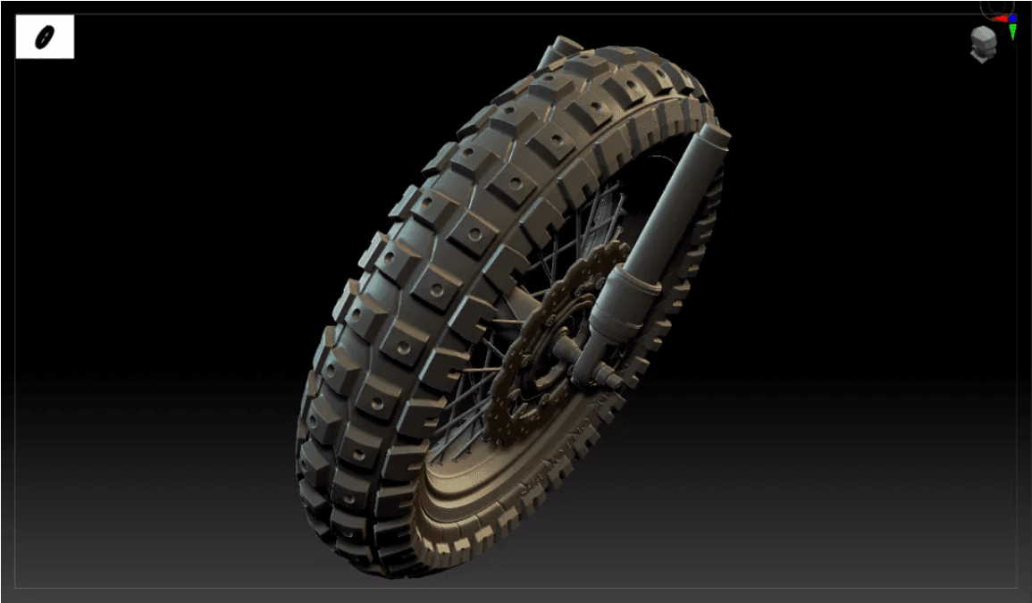
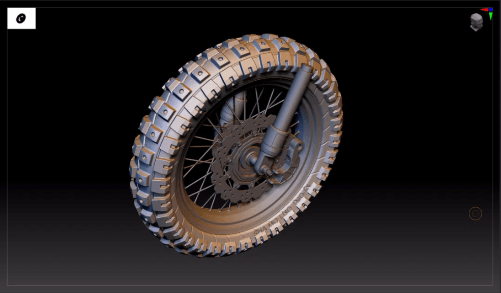
In this tutorial, Fox Renderfarm, your TPN-Accredited cloud rendering service provider and render farm, will bring a set of vehicle model making skills. This article mainly explains how to use 3ds Max and Zbrush to make high-precision models for motorcycle tire patterns and wheels to help you improve the quality and efficiency of the vehicle model.High Poly EffectThe overall process of the case:This case is a series of motorcycle production tutorials. In this tutorial, only the high poly parts of the tires and wheels are included.The outline of this tutorial is as follows:Outlinepreliminary preparation in 3ds Max and mid poly manufacturing of tireIntroduction and installation of the plug-in Radial SymmetryProduction of tire patterns and brake padsBoolean operation tire pattern in ZbrushProduction processPreparationCollect reference pictures;Create a 1:1 background board of reference picture in 3ds Max, and put the center point of the tire on the origin (0.0.0), which is convenient for model symmetry;Start to build the mid poly of the tire base. The production starts from the basic ring, adjust the inner and outer radius of the ring and the appropriate number of segments (Segments: 36, Sides16);Process decomposition:Trous \ Edit poly \ Symmetry \ Edit poly card line \ Turbo smooth 2The final effect3ds Max Plug-in, Radial SymmetryIntroduction: Radial Symmetry is a 3ds MAX modifier plug-in, which can do circular symmetry replication effect, make circular model symmetry, and the quantity adjustment is very convenient;Installation instructions:(A) Close 3ds MAX(B) Copy the corresponding version of RadialSymmetry.dlm to the plug-in folder of 3ds Max. The default example is C:\Program Files\Autodesk\3ds Max xxxx\plugins(C) Open 3ds MAX, you can see Radial Symmetry in the modifier listFunctions:(A) Radial Axis: XYZ rotation axis, this function is very important, most of the effects are adjusted here;(B) Radial Count: Number of copies(C) Smooth Seams: smooth seams(D) Quad Seams: Four-sided seams, less used(E) Mirror: double mirrorProduction of tire patterns, wheels and brake padsA. Tire 1 patternUse the topology tool to draw the pattern model, pick the tire high poly , use the Strips tool to draw the model based on the surface; the pattern is based on the reference picture;Draw pattern graphics \ shell \ pull \ symmetry \ turbo smooth \ ring symmetry;Circular symmetry: z-axis direction, Radial count: 10 pieces.B. Tire 2 patternExtract two models from the tire model and edit to the shape above;Add shell\ Edit polygon, add grooves and holes \ symmetry \ Turbo smooth \ Circular symmetry (replicate 32 times)Circular symmetry: z-axis direction, Radial count: 32 piecesZbrush effectNote: At this step, the model has not been finalized, and it needs to be imported into Zbrush for details adjustment. It is necessary to merge the pattern and the tire into one model, and the edges do a soft transition to make the model appear more realistic;
More
2022-07-01
How to Make High-precision Models For Motorcycle Tire Patterns And Wheels  in 3ds Max and Zbrush(2)
How to Make High-precision Models For Motorcycle Tire Patterns And Wheels in 3ds Max and Zbrush(2)
In this tutorial, Fox Renderfarm, your TPN-Accredited cloud rendering service provider and renderfarm, will still bring a set of vehicle model making skills.C. Wheel productionThe production of the wheel: firstly outline the cross-sectional structure;Add a lathe, an angle of 360, a number of segments of 60, and click on a subset to adjust the radius of the wheel;Add symmetry to bilateral symmetry \Edit poly card line\ Turbo smoothingD. Brake padsThe idea of making brake pads: use 2D graphics (star and round) and use 2D Boolean tools to adjust the graphics;Process: large-scale adjustments \ add circular hole \ circular copy \ extrusion thicknessThe final extrusion effect: before importing Zbrush, the model needs to be converted to poly, so that the model will not appear broken;E. Spoke structureUse the spline to make a spoke, and replicate it according to the reference picture;Select the spline to display the solid model: add Edit poly\ and turn to polyThe final effect in 3ds Max.Boolean operation pattern and drawing in ZbrushThe whole model is imported into Zbrush in the form of obj or GoZ;Create a tire folder; select the sub tool under split \ split by group; select the difference pattern; open the preview of Boolean rendering;After the preview effect goes well, select the gear icon of the tire folder, the Boolean operation folder, and generate a new Boolean model;Dynamesh: the resolution can be set to 1024 or 1280, the higher the resolution, the finer the model;Mask: According to the characteristics, the mask will be generated according to the edge of the group, the mask will be expanded once and blurred once;Inversely select the mask and select the lower polishing command. The value should be 2-3. If you want the edge to be softer, you can polish twice.Add pattern details; select the groove brush; click x key to turn on symmetry; turn on the R ring symmetry value to 10; increase pattern details;The final effect of the first pattern;The operations of the second pattern are the same as above.Note: the Boolean operation needs to select a collection and merge the model into a whole. The next steps are to dynamesh, polish, use the groove brush to increase the pattern details;The final effect of the tire
More
2022-07-01
Business Consulting

Global Agent Contact: Evan Zhang

Email: evan.zhang@foxrenderfarm.com

Marketing Contact: Evan Liu

Email: evanliu@foxrenderfarm.com

Message Us:
Newsletter
Keep up with our latest software updates, special offers and events!
Copyright © 2025 FoxRenderfarm.com. All Rights Reserved.